Understanding hull design - the lines plan
What shape is your hull? It’s a vexed question to try to answer in words, but understanding even a drawing of a three-dimensional (3D) object can be complicated.
Naval architects traditionally use what’s called a lines plan to show the shape of the hull. Although software gives us much better tools to understand the shape, curvature and continuity of a hull, the two-dimensional lines plan is invaluable - it helps us to see details that are easy to miss.
Side note: details that are easy to miss
It’s a unfortunate side-effect of modern, powerful and cheap rendering software that designs and marketing concepts are frequently presented that are unbuildable. It’s all too easy to present design designs to clients that look fabulous, but that will not survive the acid test of manufacturability, rules compliance, stability, bridge visibility requirements and so on. We have on a number of occasions seen designs presented by organisations of world-renown that are claimed to be ‘production-ready’, that actually contain flaws that will show up during manufacturing. It’s critical for the client’s time and money that the details are fully understood during the design process.
To make things clear, we’ll be looking at a possible hull design. It looks fine in the renders:

Lines plans
Lines plans show a series of lines of intersection between a surface and a plane. Imagine you are looking directly side-on to the hull, and you imagine cuts through the hull, parallel to the centre of the boat (the centre-plane, specifically). For a planing-type hull, it might look something like this:

The blue lines show where the hull intersects with the planes that are parallel to the centre-plane. These lines are called buttock-lines.
Interestingly, a couple of issues show up already, suggesting that this hull may not be as good as it needs to be: there is a curve in the bow that may not be intentional, there is a shape change aft that may also be wrong, and the detail of the lower hull in the bow looks suspect, (but we’ll check on that later).

The red arrow point to a convexity in the buttock line that indicates that the hull shape has changed in that region (compare the indicated line with it’s neighbour to the right, which has a different shape). This may well be deliberate, but it’s important to know for sure.
Note the line at the blue arrow. See how it has sloped down and aft from the bow, but towards the transom (the back of the boat) it begins to rise again slightly. This is almost invisible in the renders, but is a potential nightmare during construction.
Lines plans 2.0
So taking the idea of looking at the intersections between the hull surfaces and planes that are parallel to the center-plane, and applying it to planes that are parallel to the waterline along with planes parallel to the aft vertical plane, we get a complete lines plan:
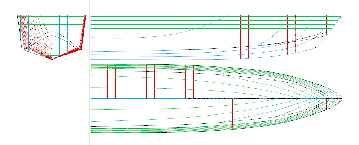
You can see that the buttock-lines that are curved in the side view (the ‘profile’ view) are straight in all the other views. The red section lines (sometimes called frame lines, stations or simply ‘sections’) tend to be split up between the front half and the back half to improve their legibility in the smaller front-on (also known as the ‘section’) view.
Note that the section view suggests that the issue at the bow that the buttock lines hinted at are real:
Note how the red section lines at the bow indicate a knife-edge detail at the bow?
This will likely lead to a hull that is difficult to build and fragile in service.

So that is a bird’s eye view of lines plans, showing how useful they can be in finding errors in hull design that may not show up without careful examination.
Stay tuned for a discussion of powerful CAD tools that help take the risk out of surfacing design.