
Hull design - CFD
Computational fluid dynamics (CFD) is the field of studying fluid flows using maths. It is an ocean of a discipline - it is wide, deep, mysterious and frustrating. it is also constantly moving - research, tool and techniques are always being improved and developed. So necessarily, this is a high-level take on how CFD can be used to design you a better boat.
CFD as a virtual towing tank
Towing tanks (or ship model basins) are places where models of marine vehicles (boats, oil rigs… ) can be tested in a controlled environment. Some tanks are long for testing pure straight-line performance, while some can generate controlled sea states to testing the dynamic behaviour of a model.
The facilities are often vital in the design process, as computer modelling is not yet fully capable of modelling hull performance with the needed accuracy.
Computers are however, excellent at providing preliminary hull design information.
The trouble with towing tanks is the need to build large models (the bigger the model the better the results - partly because the Froude and Reynolds numbers scale differently - but that’s for another day…), so to compare multiple hulls, you need to build multiple hulls, which is expensive (around US$30k each!) and time consuming.
Testing a design using CFD allows multiple options to be compared in a much more timely and cost effective way. Once the hull has been optimised, it can then have its absolute performance characteristics determined in a towing tank.
So how does it work?
By and large (ignoring technologies like smoothed particle hydrodynamics), CFD uses a grid of cells (a little like FEA) to evaluate how the fluid moves.
The grid structure depends on the type of analysis you’re doing. Initial design will frequently use potential flow analysis, which ignores turbulence effects assuming that the flow is frictionless and irrotational, but solves quickly which is handy for initial optimisation. This grid tends to only model the water, and primarily solves the continuity equations for the flow (what comes in to a grid cell must go out).
Beyond the potential flow solution is traditionally the mouthful of the six-degree-of-freedom-Reynolds-averaged-Navier-Stokes solution, or RANS for short. This approach accounts for turbulence and viscosity effects and thus takes much longer to solve, and can lead to instabilities which can thwart the solver altogether. Turbulence modelling is also an evolving field.
[ Quick aside: Recalling your high-school science, do you remember Newton’s second law written as F = ma? Saying that the force applied to a system is equal to its mass times its acceleration is another way of describing the conservation of momentum in a system. Think of it as saying that force and change of momentum always balance. Now generalise that idea to cover not only momentum, but also mass and energy, and you get the Navier-Stokes equations. If you decide to simplify it a bit to ignore viscosity and turbulence, and you get the Euler equations of the potential flow analysis mentioned above! Neat, no? ]
CFD is great at understanding the nuances of the flow. See in the images below how the streamlines move along very different paths with only slight changes in position.
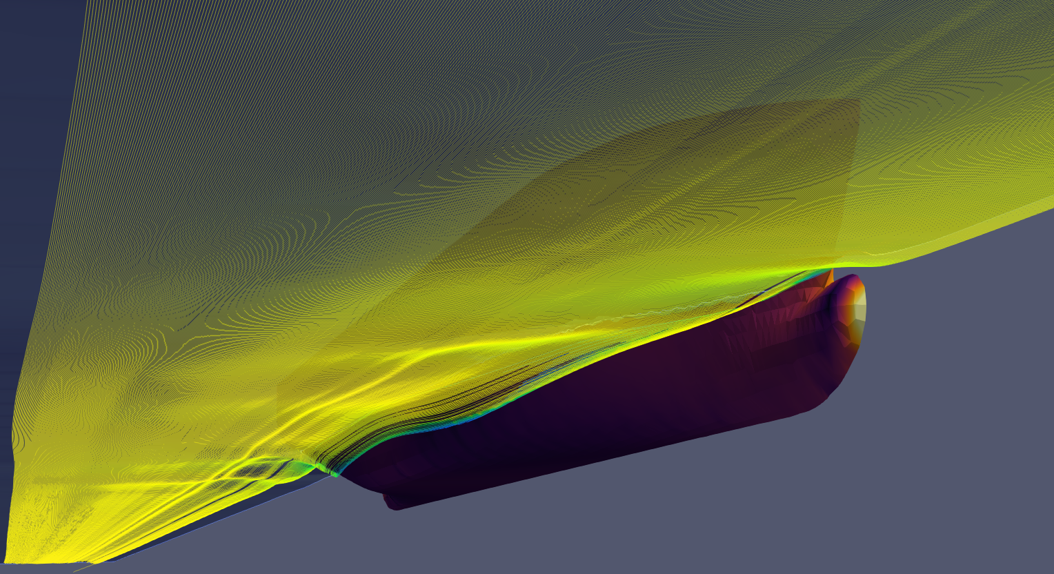
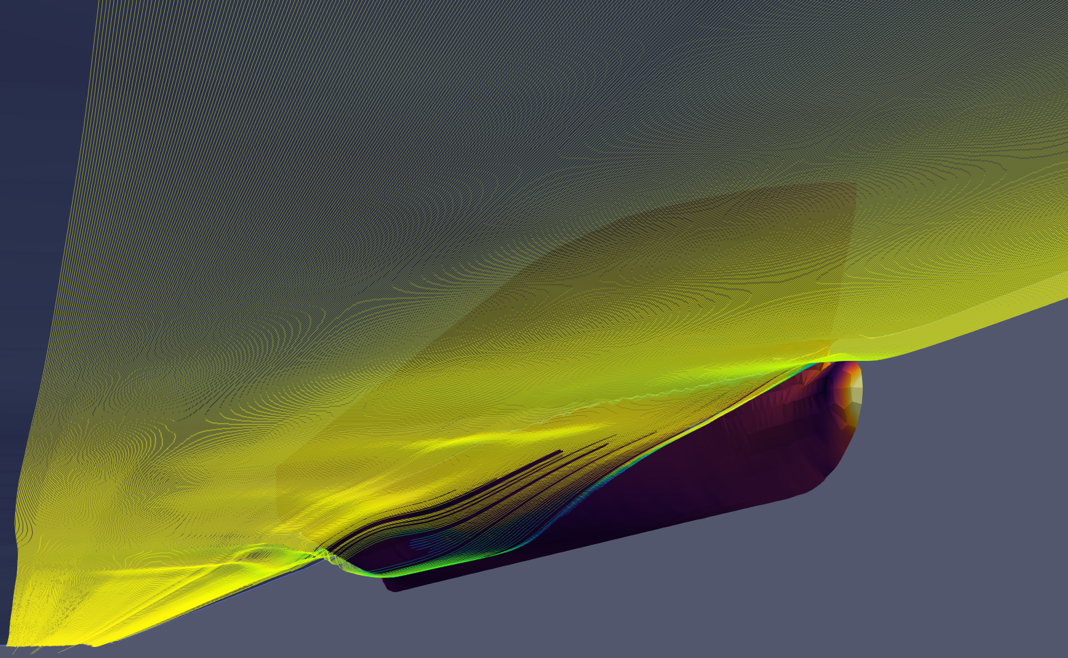
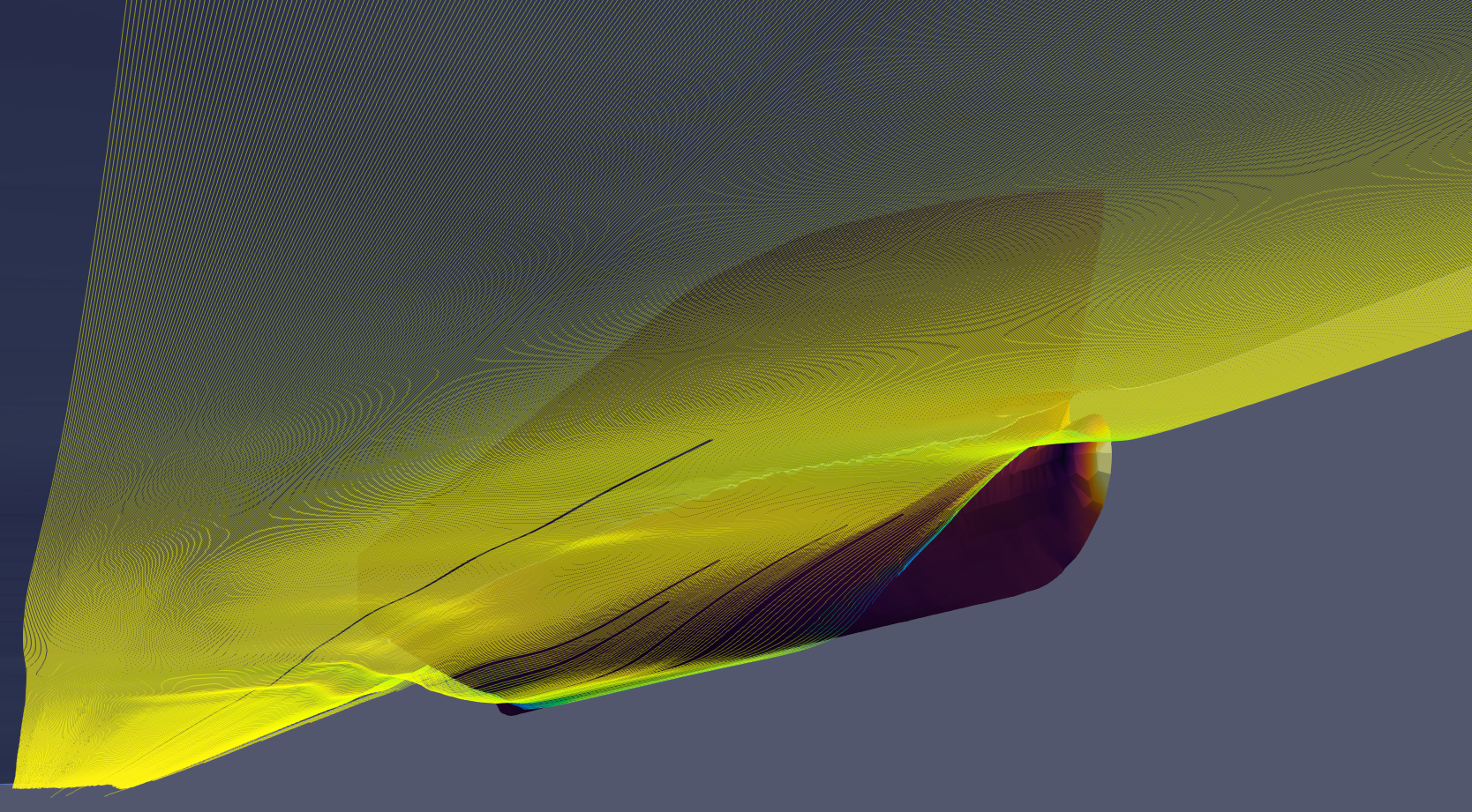
…in the leftmost image, the streamlines show flow close to the free surface, while as the start points of the streamlines are moved lower (images to the right), they very quickly wrap around under the hull.
This can be important for the design of propellers, rudders, bilge keels and anti-roll fins, seawater cooling locations, deck drains, general overboards and near-water exhaust outlets.
CFD as a virtual wind tunnel
CFD can also be used to study air flow. This is particularly important for locating HVAC air in and out locations, galley ventilation and above-water exhaust flows for main engines and gensets.
The image to the right shows a study of the air flows around a semi-open custom vessel, designed for Sydney Harbour and it’s near-coastal surrounds.

So CFD provides a powerful tool for understanding the flows around hulls and superstructures in a unique way. It’s possible to ‘fly through’ the results of a study to see and understand details that would simply not be possible in the non-virtual world.
It’s ability to allow for efficient and effective design iterations, and to also provide unique insights into a design make it essential for much design work, and handy for all.
I hope you’ve found this helpful.
Take care,
Nick.